
How to Use a Digital Multimeter: Step-by-Step Guide for Beginners & Electricians
Table of ContentsStep-by-Step Tutorial 2025
A complete multimeter tutorial covering every measurement type — voltage, current, resistance, continuity, capacitance & more. Includes essential safety tips every professional in the UAE must know.
Learning how to use a digital multimeter is one of the most fundamental skills for anyone working with electricity — from first-year apprentice electricians to seasoned maintenance engineers. A digital multimeter (DMM) lets you measure voltage, current, resistance, and much more, making it the single most versatile diagnostic tool you'll ever own.
Yet, despite being one of the most common tools in the trade, many professionals never received formal training on proper multimeter use. They pick up habits — some good, some dangerous — from watching colleagues on the job. Incorrect multimeter use is one of the leading causes of equipment damage, inaccurate diagnoses, and in worst cases, serious electrical injuries.

This comprehensive multimeter tutorial walks you through every measurement type step-by-step, with clear instructions, multimeter safety tips you must follow, common mistakes to avoid, and practical examples relevant to electricians working in the UAE's 230V/400V electrical systems. Whether you're a complete beginner or an experienced electrician looking to refresh your knowledge, this DMM guide for electricians has you covered.
1. Parts of a Digital Multimeter Explained
Before you take any measurements, you need to understand the basic parts of a digital multimeter. While models vary between brands, every DMM shares these core components:
1.1 Display Screen
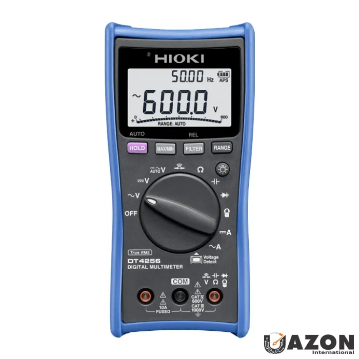
Shows the numerical measurement reading, measurement unit (V, A, Ω), selected mode, battery status, and additional indicators. Most professional multimeters like the Hioki DT4256 feature backlit LCD displays with bar graphs for seeing signal trends.
1.2 Rotary Dial (Function Selector)
The large dial in the center of the meter selects what you want to measure. Common positions include:
- V⎓ or V DC — DC Voltage
- V~ or V AC — AC Voltage
- A⎓ or A DC — DC Current
- A~ or A AC — AC Current
- Ω — Resistance
- 🔊 (sound wave icon) — Continuity
- ▶| — Diode Test
- F — Capacitance
- Hz — Frequency
- OFF — Power off
💡 Auto-Range vs Manual Range: Modern multimeters like the Fluke 87V and Hioki DT4256 are auto-ranging — they automatically select the correct measurement range. Older or budget models may require you to manually select the range (200V, 600V, 1000V, etc.). Auto-range saves time and eliminates the risk of selecting the wrong range.
1.3 Input Jacks (Ports)
These are the sockets where you plug in your test leads. Most multimeters have three or four jacks:
1.4 Test Leads (Probes)
The red and black cables with probe tips. The black lead always connects to COM. The red lead moves between the V/Ω and A jacks depending on what you're measuring. Quality test leads with proper insulation ratings are essential for safety — always inspect them before use.
1.5 Function Buttons
Most modern DMMs have additional buttons for features like:
- HOLD — Freezes the current reading on the display
- RANGE — Switches between auto-range and manual range
- MIN/MAX — Records minimum and maximum readings
- REL (Δ) — Sets the current reading as a reference point (relative mode)
- LIGHT — Turns on the backlight or built-in flashlight
2. Essential Safety Rules — Read This First!
🔴 CRITICAL: Multimeter Safety Tips You Must Follow
Electricity is unforgiving. These multimeter safety tips are not suggestions — they are rules that protect your life. Follow them every single time, without exception:
Rule #1: Inspect Before You Use
- Check test leads for cracked, damaged, or melted insulation
- Ensure probe tips are not bent, broken, or exposed beyond the insulated tip
- Verify the meter is not physically damaged (cracked case, broken dial)
- Check battery level — low battery = unreliable readings
- Replace damaged leads immediately — never tape or patch them
Rule #2: Use the Correct CAT-Rated Meter
Ensure your multimeter is rated for the environment you're working in. For UAE electrical systems (230V/400V):
- Working at outlets/appliances: Minimum CAT II 600V
- Working at distribution panels: Minimum CAT III 600V
- Working at main service entrance: Minimum CAT IV 600V
Professional meters like the Hioki DT4256 (CAT IV 600V / CAT III 1000V) and Fluke 87V (CAT IV 600V / CAT III 1000V) exceed these requirements.
Rule #3: Never Measure Current in Parallel
This is the most dangerous mistake. When measuring current (Amps), the meter must be connected IN SERIES (breaking the circuit and inserting the meter in the path). Connecting a meter set to current mode across a voltage source creates a dead short through the meter's near-zero internal resistance, which can cause:
- Internal fuse to blow
- Arc flash explosion
- Severe burns or electrocution
- Destruction of the meter
Rule #4: Start with the Highest Range
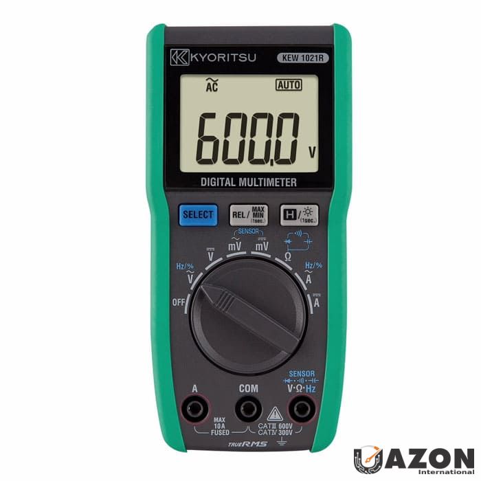
If using a manual-range meter, always start with the highest voltage/current range and work down. This prevents overloading the meter. With auto-ranging meters like the Kyoritsu 1021R, this is handled automatically.
Rule #5: De-Energize Before Measuring Resistance
NEVER measure resistance (Ω) or continuity on a live circuit. The meter injects a small test current to measure resistance — if the circuit is live, you'll get incorrect readings and may damage the meter. Always confirm the circuit is de-energized first using a voltage measurement.
Rule #6: One Hand Rule
When possible, operate the meter and probes with one hand while keeping the other hand in your pocket or behind your back. This prevents current from flowing across your chest (through your heart) in case of accidental contact with live parts.
Rule #7: Check Leads Are in the Right Jacks
Before every measurement, visually confirm the red lead is in the correct jack for your selected measurement. Meters with wrong-input protection like the Hioki DT4256 will alert you if the leads are in the wrong jack — but not all meters have this feature.
⚠️ UAE Context: All electrical work in the UAE must comply with local authority regulations (DEWA in Dubai, ADDC in Abu Dhabi, SEWA in Sharjah, FEWA in northern emirates). Always follow your employer's safety procedures, wear appropriate PPE, and hold the necessary EWIS or equivalent electrical work permit before working on live systems.
3. Setting Up Your Multimeter — Leads, Jacks & Dial
Proper setup is the foundation of accurate measurement. Here's the universal setup process that applies to every digital multimeter:
Step 1: Insert Test Leads
- Black lead → COM jack (always — this never changes)
- Red lead → V/Ω jack (for voltage, resistance, continuity, diode, capacitance, frequency)
- Red lead → mA or 10A jack (ONLY for current measurement — move it back when done)
Step 2: Select the Function
Turn the rotary dial to the measurement function you need (V~, V⎓, Ω, A, etc.)
Step 3: Select the Range (Manual Range Meters Only)
If your meter doesn't auto-range, select a range higher than the expected value. For example, to measure UAE mains voltage (~230V), select the 600V range.
Step 4: Take the Measurement
Touch the probe tips to the measurement points and read the display.
Step 5: After Measurement
Remove probes from the circuit, turn the dial to OFF (or the highest voltage range if no OFF position), and return the red lead to the V/Ω jack if you moved it for current measurement.
💡 Pro Tip: Develop a habit of always returning the red lead to the V/Ω jack after measuring current. Many meters have been destroyed (and many fuses blown) because the user left the lead in the A jack, then tried to measure voltage. The Hioki DT4256's wrong-input alert is designed specifically to catch this mistake.
4. How to Measure AC Voltage
Measuring AC voltage is the most common task you'll perform with a multimeter, especially in the UAE where the standard mains supply is 230V single-phase and 400V three-phase at 50 Hz. Here's how to measure voltage with a multimeter correctly:
Step-by-Step: AC Voltage Measurement
- Insert the black lead into the COM jack
- Insert the red lead into the V/Ω jack
- Turn the rotary dial to V~ (AC Voltage)
- Touch the probe tips to the two points you want to measure across:
- Phase to Neutral: Should read approximately 230V in UAE
- Phase to Phase: Should read approximately 400V in UAE
- Phase to Earth: Should read approximately 230V in UAE
- Neutral to Earth: Should read close to 0V (a few volts is normal)
- Read the display — the meter will show the RMS voltage value
What Do the Readings Mean?
⚠️ Important: AC voltage readings on circuits with VFDs, inverters, or electronic dimmers may appear inflated if you're using an average-responding meter. For accurate readings on these circuits, always use a True RMS multimeter. Models like the Hioki DT4256, Fluke 87V, and Kyoritsu 1021R are all True RMS meters. For VFD motor output measurements, use the Low-Pass Filter (LPF) function if available to see the fundamental voltage.
5. How to Measure DC Voltage
DC voltage measurement is used for batteries, solar panels, electronic circuits, control circuits, and DC power supplies. The process is similar to AC voltage with one key difference — polarity matters.
Step-by-Step: DC Voltage Measurement
- Black lead → COM jack
- Red lead → V/Ω jack
- Turn the dial to V⎓ (DC Voltage)
- Touch the red probe to the positive (+) terminal and the black probe to the negative (−) terminal
- Read the display — a positive reading confirms correct polarity; a negative reading means you have the probes reversed (not dangerous, but flip them for correct polarity indication)
Common DC Voltage Measurements
6. How to Measure Resistance (Ohms)
Resistance measurement tells you how much a component or conductor opposes the flow of electricity. It's used for checking resistors, motor windings, heating elements, and verifying wire integrity.
🔴 CRITICAL SAFETY: ALWAYS de-energize the circuit before measuring resistance. Disconnect the component from the circuit if possible. Measuring resistance on a live circuit will give false readings and may damage your meter.
Step-by-Step: Resistance Measurement
- De-energize the circuit and discharge any capacitors
- Disconnect the component from the circuit (at least one end) to avoid parallel path readings
- Black lead → COM, Red lead → V/Ω
- Turn the dial to Ω (Resistance)
- Touch probe tips across the component or wire
- Read the display — the unit will show Ω, kΩ, or MΩ depending on the value
Interpreting Resistance Readings
- 0 Ω (or very low): Short circuit or very low resistance — wire, fuse, or closed switch
- Expected value (e.g., 1kΩ, 10kΩ): Component is within specification
- OL (Over Limit / Open Loop): Infinite resistance — open circuit, broken wire, blown fuse, or open switch
💡 Using REL (Relative) Mode: The test leads themselves have a small resistance (typically 0.1–0.5Ω). For precise low-resistance measurements, first short the probe tips together, press the REL/Δ button to zero out the lead resistance, then measure the component. This technique is available on the Hioki DT4256, Fluke 87V, and most professional DMMs.
7. How to Test Continuity
Continuity testing is essentially a pass/fail resistance test with an audible buzzer. If there's a complete electrical path (low resistance), the meter beeps. If the path is broken (open circuit), there's no beep. It's the fastest way to check if a wire, fuse, or switch is intact.
Step-by-Step: Continuity Test
- De-energize the circuit completely
- Black lead → COM, Red lead → V/Ω
- Turn the dial to the continuity symbol (🔊 sound wave icon)
- Touch probe tips across the component, wire, or connection you want to test
- Listen for the beep:
- Continuous beep = Good continuity (circuit is complete)
- No beep = Open circuit (break in the path)
- Verify your meter works first: Touch the two probe tips together — you should hear a beep. If not, check the battery or leads
Common Continuity Tests
- Wire integrity: Test from one end of a cable to the other to confirm no breaks
- Fuse testing: Touch probes across a fuse — beep = good, no beep = blown
- Switch testing: Close the switch, test across it — should beep when ON, no beep when OFF
- Motor winding: Test between winding terminals — should beep (low resistance path)
- Earth continuity: Verify equipment earthing is connected back to the earth bar
8. How to Measure DC Current
Current measurement requires the most care of any multimeter function because you must break the circuit and insert the meter in series. This is the measurement that causes the most multimeter damage when done incorrectly.
🔴 WARNING — Read Before Proceeding
- The multimeter must be connected IN SERIES with the load — NEVER across (in parallel with) a voltage source
- The red lead must be in the correct current jack (mA for small currents, 10A for large currents)
- If you're unsure about the current level, start with the 10A jack and switch to mA only after confirming the current is low enough
- For measuring current above 10A, use a clamp meter instead — it doesn't require breaking the circuit
Step-by-Step: DC Current Measurement
- De-energize the circuit
- Black lead → COM
- Red lead → 10A jack (if you expect more than ~400mA) or mA jack (for smaller currents)
- Turn the dial to A⎓ (DC Current)
- Break the circuit at the point where you want to measure current — disconnect one wire
- Connect the meter in series — one probe to each end of the break so the circuit current flows THROUGH the meter
- Re-energize the circuit
- Read the current on the display
- De-energize, disconnect the meter, reconnect the original wire, and move the red lead back to V/Ω jack
💡 Easier Alternative: For most current measurements, especially on AC power circuits, a clamp meter is much safer and more convenient because it doesn't require breaking the circuit. Simply clamp it around the conductor. See our complete guide: Clamp Meters Explained — Complete Buying Guide for UAE
9. How to Measure AC Current
The procedure for measuring AC current is identical to DC current, except you select A~ (AC Current) on the dial. The same safety warnings apply — series connection only, correct jack, and be extremely cautious.
⚠️ Practical Reality: In professional practice, almost nobody measures AC current above a few amps using a multimeter because breaking a live power circuit to insert a meter is dangerous and impractical. Instead, professionals use clamp meters that measure current by clamping around the conductor. If you regularly need current measurements, invest in a good clamp meter in addition to your DMM. Browse our clamp meter range at Uazon.ae
10. How to Measure Capacitance
Capacitance measurement is particularly useful for HVAC technicians testing motor run and start capacitors — one of the most common component failures in UAE's air conditioning systems.
🔴 Safety First: Capacitors store electrical energy even after the circuit is de-energized. Always discharge capacitors before testing by shorting the terminals together through a resistor (e.g., 10kΩ, 5W). Never short directly — large capacitors can produce dangerous sparks.
Step-by-Step: Capacitance Measurement
- De-energize the circuit and remove the capacitor
- Discharge the capacitor safely
- Black lead → COM, Red lead → V/Ω
- Turn the dial to capacitance mode (F symbol or ─┤├─)
- Touch probe tips to the capacitor terminals
- Wait a few seconds for the reading to stabilize
- Compare the reading to the capacitor's rated value (printed on its body). A capacitor is typically considered failed if the measured value is more than ±10–20% from its rated value
Example: A motor run capacitor rated at 35μF should read between approximately 28μF and 42μF. If it reads 15μF or shows OL (open), replace it. This is one of the most common HVAC repairs in UAE.
11. How to Test a Diode
The diode test function checks whether a diode (or the diodes inside a bridge rectifier) is working correctly by measuring its forward voltage drop.
Step-by-Step: Diode Test
- De-energize and disconnect the diode from the circuit
- Black lead → COM, Red lead → V/Ω
- Turn the dial to diode mode (▶| symbol)
- Forward test: Red probe to anode (+), black probe to cathode (−) → Should read 0.5V–0.7V for silicon diode
- Reverse test: Swap probes → Should read OL (no conduction)
- Interpreting results:
- Good diode: ~0.5–0.7V forward, OL reverse
- Shorted diode: ~0V both directions
- Open diode: OL both directions
12. How to Measure Frequency
Frequency measurement (Hz) is available on advanced multimeters like the Hioki DT4256 and Fluke 87V. It's used to verify the power supply frequency, check generator output, and diagnose electronic control signals.
Step-by-Step: Frequency Measurement
- Black lead → COM, Red lead → V/Ω
- Turn the dial to Hz (Frequency) or press the Hz button while in AC voltage mode
- Touch probes across the signal source
- Read the frequency — UAE power supply should read 50.0 Hz (±0.5 Hz is normal)
When to use: Checking standby generator frequency output (should stabilize at 50 Hz), verifying UPS output frequency, testing speed controller signals, and diagnosing equipment that is sensitive to frequency variations.
13. Advanced Features — Data Hold, Min/Max, REL & LPF
Modern professional multimeters include powerful features that many users never take advantage of. Here's how to use the most useful advanced functions:
📌 Data Hold (HOLD)
What it does: Freezes the current reading on the display.
When to use: When you're measuring in a position where you can't see the screen — like reaching inside a dark panel or working overhead. Press HOLD while the probes are still connected, then withdraw the meter to read the frozen value.
📊 Min/Max Recording
What it does: Continuously records the minimum and maximum values measured since the function was activated.
When to use: Diagnosing intermittent problems. Leave the meter connected and activate Min/Max — come back later to see if the voltage dropped below or spiked above normal. Essential for catching loose connections that cause intermittent voltage drops, or voltage spikes from switching events.
Δ Relative Mode (REL)
What it does: Stores the current measurement as a baseline and displays subsequent measurements as the difference from that baseline.
When to use:
- Zeroing out test lead resistance for precise low-ohm measurements
- Monitoring changes from a known reference value
- Comparing multiple components against a standard
🔉 Low-Pass Filter (LPF)
What it does: Blocks high-frequency components (above ~1 kHz) from the measurement, showing only the fundamental 50 Hz voltage.
When to use: Measuring the true voltage output of Variable Frequency Drives (VFDs). Without LPF, the high-frequency switching components of a VFD output can inflate the voltage reading by 20–50%. With LPF enabled, you see the actual fundamental motor voltage. Available on the Hioki DT4256 and Fluke 87V.
🔦 Built-in Flashlight
What it does: LED light on the meter body illuminates the work area.
When to use: Working in dark panels, cable trays, ceiling voids, and under-floor spaces. The Hioki DT4256 features a built-in flashlight that's more practical than you'd think — it means one less tool to carry.
14. 10 Common Multimeter Mistakes (And How to Avoid Them)
Even experienced professionals make these mistakes. Being aware of them can save your equipment, your time, and potentially your life:
15. Recommended Multimeters for UAE Professionals
Now that you know how to use a digital multimeter, here are our top recommendations available at Uazon.ae:
🏆 Best Overall — Hioki DT4256
The Hioki DT4256 is our #1 pick for professionals who want a meter that handles every measurement described in this guide. True RMS, CAT IV 600V, auto-range, LPF, wrong-input protection, frequency, duty cycle, capacitance, built-in flashlight, and drop-proof construction. This is the meter we used as the reference throughout this tutorial.
Best for: General electricians, industrial maintenance, building services engineers
⭐ Industry Standard — Fluke 87V
The Fluke 87V is the world's most trusted industrial multimeter. 20,000-count display, True RMS, built-in thermometer, selectable LPF, and legendary Fluke ruggedness. If your company standardizes on Fluke equipment, this is the meter to have.
Best for: Industrial electricians, motor/VFD troubleshooting, premium professional use
💰 Best Value — Kyoritsu 1021R
The Kyoritsu 1021R delivers professional-grade True RMS measurement at an accessible price. 6000-count, CAT III 600V, auto-range, and reliable Japanese quality. Perfect for electricians who want a dependable professional meter without the premium price.
Best for: Value-conscious professionals, field electricians, electrical contractors
🔧 Best Budget — Marmonix MUT-520S
The Marmonix MUT-520S proves you don't need to spend a fortune to get a functional digital multimeter. It covers all the basic measurements described in this guide — voltage, current, resistance, continuity — at an unbeatable price. Ideal for students, hobbyists, and as a backup meter.
Best for: Beginners, students, hobbyists, backup meter, basic residential checks
📖 For a comprehensive comparison of these and other models, read our pillar guide: The Ultimate Guide to Digital Multimeters — How to Choose, Use & Buy the Best DMM in UAE
📖 For a detailed Hioki comparison: Hioki DT4256 vs DT4253 vs DT4252 — Which Is Right for You?
16. Frequently Asked Questions
Uazon.ae — UAE's Trusted Source for Professional Test & Measurement Instruments
Genuine instruments from Hioki, Kyoritsu, Marmonix & more. Delivery across UAE — Dubai, Abu Dhabi, Sharjah & all Emirates.