

Description
About this model
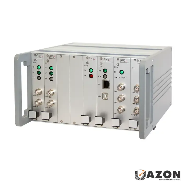
Advanced Partial Discharge Detection with the Megger ICM System Generation 5
The Megger ICM system Generation 5 sets a new standard in partial discharge (PD) detection technology, delivering unmatched precision, reliability, and versatility for high-voltage insulation testing and monitoring. Designed for electrical engineers, asset managers, and maintenance professionals, this advanced system safeguards critical infrastructure by detecting insulation defects before they evolve into costly failures. If you are looking to buy the Megger ICM system Generation 5, understanding its technical capabilities is the first step toward securing your assets.
For those evaluating the Megger ICM system Generation 5 price, the investment is justified by the system's ability to prevent downtime and extend the lifespan of high-voltage equipment. This solution is engineered to provide actionable insights that optimize maintenance schedules and improve operational reliability across various industrial applications.
Technical Features and Field Applications of the Megger ICM System Generation 5
The modular, scalable design of the ICM system Generation 5 allows it to be tailored to a wide range of high-voltage assets. Whether monitoring transformers, switchgear, cables, generators, or gas-insulated systems (GIS), the system adapts to specific operational requirements. Its advanced hardware components are paired with intelligent software that enables real-time PD data acquisition, analysis, and visualization.
- Modular and scalable system design for use across transformers, switchgear, cables, generators, and GIS
- Real-time data acquisition with advanced noise suppression for reliable results in noisy environments
- High-sensitivity partial discharge (PD) measurement for accurate detection of insulation defects
- Compatible with a wide range of sensors and accessories for flexible deployment
Why the Megger ICM System Generation 5 Is the Best Price Investment
When considering the best price for partial discharge monitoring equipment, the Megger ICM system Generation 5 stands out due to its high-sensitivity measurement capability combined with sophisticated noise suppression. This feature enables clear differentiation of true partial discharge signals from environmental and electrical noise, ensuring accurate diagnostics even in challenging industrial environments. The ability to detect micro-coulomb-level discharges makes it a superior choice for critical asset monitoring.
The system’s intuitive user interface and software suite simplify the process of testing, data collection, and reporting. This accessibility makes it suitable for both field engineers and laboratory professionals. By generating reports quickly with detailed graphical representation, trend analysis, and historical comparison, the system supports proactive decision-making and compliance with international testing standards.
Key Benefits of the Megger ICM System Generation 5
Understanding the practical benefits of the Megger ICM system Generation 5 is essential for asset managers and maintenance professionals. The following features translate directly into operational improvements and cost savings.
- Early detection of insulation defects to prevent costly downtime and catastrophic failures
- High sensitivity PD measurement for reliable identification of defects at micro-coulomb levels
- Modular and scalable design for versatile applications across high-voltage assets
- Real-time monitoring with advanced noise suppression and data analytics for noisy environments
- Intuitive interface for easy operation and rapid reporting, reducing training time
- Suitable for on-site testing, laboratory analysis, and permanent monitoring solutions
Operational Capabilities and Environmental Suitability
The Megger ICM system Generation 5 is engineered to perform reliably in diverse environments. Its technical specifications ensure that it meets the rigorous demands of modern electrical infrastructure monitoring. The system's design prioritizes durability and accuracy, making it a trusted tool for critical diagnostics.
- Measurement frequency range: 30 kHz – 100 MHz (depending on sensor configuration)
- PD sensitivity: Detects micro-coulomb-level discharges for precise fault identification
- Sampling rate: High-speed real-time acquisition for capturing transient events
- Noise suppression: Advanced filtering algorithms for accurate signal differentiation in industrial settings
- Data storage: Internal memory with export capability for long-term monitoring and trend analysis
- Connectivity: USB/Ethernet for seamless software integration and remote monitoring
- Operating temperature: -10°C to 50°C, suitable for field and laboratory use
- Compliance: Meets international PD testing standards (IEC 60270, IEEE, and others)
Comprehensive Reporting and Software Integration
The software suite included with the Megger ICM system Generation 5 is designed to maximize the value of collected data. It transforms raw PD measurements into clear, actionable insights that support maintenance planning and compliance reporting.